When you click on links to various merchants on this site and make a purchase, this can result in this site earning a commission. Affiliate programs and affiliations include, but are not limited to, the eBay Partner Network.
Thanks for the compliment. I chose a Champion 3-row radiator with 5/8" tubes. The Champion has square side tanks so I had to modify the top & bottom saddles to get the radiator to fit. I had some quality issues with the first 2 radiators I received, they were out of square which caused issues fitting the electric fan shroud to the radiator. Champion hand selected a 3rd radiator for me and checked the squareness before shipping. I've heard some say the 3-row, 5/8' tube radiators do not cool as well as the 2-row, 1" tube radiators. I don't have any road miles on my car yet so I can't say if this is true.
I tried to buy a windshield from Safelite Glass but they wouldn't do an on-site installation because of the age of the car. My car isn't registered or tagged to be driven on the street so it would have required two flatbed tow trips to get the car to the glass company and back home. I also don't have the convertible top on yet and didn't want to risk an afternoon thunderstorm while the car being parked outside. So I called an "old school" local glass supplier who's been in business since the late 50's and ordered a windshield from them; it arrived on Friday and the tech is coming on Tuesday to install it so I had a few tasks to complete before the windshield. My tasks were as follows: 1. Install the vinyl wrap on the windshield header, 2. fit interior windshield header trims and 3. fit the inside and outside A-pillar trims.
I purchased the vinyl from a trusted member here and was all set to install it using 3M 80 Vinyl & Rubber adhesive, but I decided to do a Google search and discovered there is a special, high-heat contact cement made by DAP/Weldwood designed for vinyl & landau tops. A quick trip to Amazon.com and it was at my door in 5 days. How did we restore these cars before the internet? The header vinyl was a total PITA to install; the DAP spray can had a hair trigger, and the spray pattern was really large and difficult to predict which way it would spray. I guess if you're doing a full vinyl top this might not be a problem but for the relatively small windshield header it was a bit like trying to wash your car with a firehose! Fortunately, I had masked off everything pretty well to protect from the overspray. I finally landed on a technique that was much more predictable, I sprayed the adhesive into a small plastic bowl and used a Q-tip to apply to both sides. It's important to apply to both pieces, press together then separate for 30 seconds until the glue gets tacky then recombine and hold for a few seconds more. Cleanliness is a must when doing this project; once you get this stuff on your fingers, you'll be sticking to everything you touch. WD-40 is an excellent solvent to remove the excess glue from your fingers and from the vinyl and won't hurt the vinyl material. I started in the middle of the header and worked my way outward, I did the LH side first being careful not to cut too much material away, and practiced the folds before applying the glue. The learning curve on the LH side was pretty steep, the RH side went much faster,
EDIT: This DAP stuff is total crap. The header vinyl is pulling loose and already has bubble spots; it hasn't even been in the sun! I would no recommend this product.
I've run into to a small issue when fitting the A-pillar pieces. There are 2 pieces that mount to the outside of the A-pillar; the large wide stainless piece goes on first and is part of the windshield revel moldings, but there is a second piece that holds the rubber weatherstriping that goes on top but I can't figure out how it gets attached. There are "open" screw holes in the structural A-pillar but they don't seem to line up with any holes in the trim. I'm going to start a separate thread with this question to see if any other members can help me out.
Here's some pics:
Rodney
I was planning to use the 3M 80 adhesive, but learned about the DAP product from a Chevelle forum.
I put blue painters tape along the bottom side of the windshield to keep the contact cement off this area. I carefully cut slits in the vinyl at the mounting studs.
I think it turned out great.
Here's a shot showing the interior header trims.
The interior A-pillar trims look a bit bent at the bottom. I may need to bend these down a bit, but I'll wait until the dash is installed to get a better perspective.
It's not really clear how this piece with the weatherstriping mounts to the A-pillar.
There are screw holes in the A-pillar and holes in the trim - see the red arrows, but they do not line up in any way that makes sense.
There is a mounting hole in the rubber and a slot in the metal trim; maybe the rubber needs to slide down in the metal trim to be inside the slot??
Does the metal need to be higher? See red arrows.
The rubber and metal seem to fit well at the bottom.
Last edited by cdrod; October 21st, 2023 at 07:34 AM.
The new windshield is installed. In Texas, our vehicle registration sticker is installed on the windshield, so having a windshield means I'm that much closer to getting this 11 year long project on the road again. The first windshield they brought had a large scratch on the inside of the glass, deep enough that you could catch it with your fingernail. Fortunately, the glass shop was able to source another part in just a few days. I figured out the the correct placement of the weatherstrip channel by researching photos online of convertibles. The online photos showed this part installed much higher than I had thought.
The tweeter speakers I added are pretty close to the glass so I'm not sure how good they will sound. The primary front speakers will be mounted in the doors, near your feet so these dash tweeters will be used for "front fill" to lift the sound stage up. I had a little problem with the bright molding that spans the top of the windshield; it seems I grabbed the wrong molding from my storage unit. The part that I cleaned and polished is about 2" inches too short and is for a hardtop or coupe. Convertible windshields are not the same; they are 51" long whereas the hardtop molding is only 49" long. I'm currently looking for a suitable replacement. Pics are posted below.
Rodney
I figured out the placement of the weatherstrip channel. It's installed higher than I thought.
Once the weatherstrip channel was raised up to the correct location, the screw holes mostly lined up.
The weatherstrip channel needs a foam seal applied to the backside before installation. The strip is available as a "peal & stick" product from Inline Tube. I masked off this area and used my sand blaster to remove the old foam material.
The dash tweeters I added as very close to the glass. They will provide "front fill" to lift the sound stage up from the door speakers.
Here's a side shot of the tweeter from the inside.
The top piece of bright molding was too short, I discovered the convertibles have a longer molding across the top of the windshield and it has a different curvature. Hardtop/coupe part is on the LH side, convertible is on the RH side.
This picture shows the difference in the curvature; convertible part is on top, hardtop/coupe part is the bottom.
The correct part for a convertible should be 51" long.
Last edited by cdrod; August 2nd, 2023 at 12:21 PM.
Today I installed most of the side window glass. Back in Post #185, I showed the power window wiring harness using DEI535 window control module. These modules provide a "one-touch" up & down function that will be a nice feature for my convertible; unfortunately, they require reversible motors where up & down switches polarity of a single motor winding. The stock window motors have two windings; one for up and another for down. Another nice feature of the DEI window module is remote control. Using the Viper alarm I can program aux channels to control additional things; like the trunk release and lower all the windows using the key fob.
To use the DEI535 modules I had to retrofit late model window motors from 1980s G-body cars to the early A-body window regulators. I drew up some adapters in CAD and made adapters from heavy gauge sheet steel. It was a bit tricky to get the gear pinion of the late model motors to line up with the hole in the regulator plate; it took a few iterations and test fittings before I finally had something that worked. I clocked the motors to have a slight downward pitch to keep water out of the motor connectors. The motors, connector pig-tails & window switches were manufactured by Dorman and easily sourced from Rock Auto and Amazon.
Here's some pics:
Rodney
This is final cardboard template (one of many).
I used three 3/8" bolts to mount the adaptor plate to the stock regulator assembly and stainless machine screws with hex stand-offs to mount the motor.
The adaptor ready to mount to the regulator.
Ready to receive the motor.
The motor is secured in place with 3 nylock lock nuts.
This is the quarter regulator with motor. I mocked this up while the quarter panel was removed from the car.
This is the LH door regulator: this side mounts to the inner door sheetmetal,
The same LH door regulator showing the motor side.
A single DEI module can provide "one-touch" down functionality to 4 windows or "one-touch" in the up & down direction for 2 windows. This is the rear module mounted inside the interior quarter trim; there is a 2nd module tucked inside the dash to control the front windows.
Last edited by cdrod; August 7th, 2023 at 11:21 AM.
In replacing the door and quarter window glass, I discovered the retainers and stops were very rusty. I know this is an area that would not be seen, but I live in a very humid climate and I was concerned about the longevity of my work. It seemed best to restore this hardware and by documenting the process I may help someone in the future identify the location and orientation of these fasteners.
This is the rear guide of the LH door glass viewed from the inside. All the fasteners and guides were rusty.
This the front guide for the LH door glass.
There was even more rust lurking between the pieces.
After media blasting and some industrial grade rattle can paint. I baked the parts in a small toaster/convection oven for about 2 hours at 250-300 degrees; really hardened the paint.
The new door glass ready for installation. The three circular fasteners have 1/4" studs that mount it to the regulator and there is a bit of play in the placement of these studs. I used an extra regulator to align the studs before tightening them to the new glass.
Close up of the restored hardware.
I bought some fabric from Ames Performance to restore these door glass guides. After stripping and painting, I used 3M adhesive to glue the new fabric strips in place. Two #8 stainless screws and they were ready for service.
This is my next window guide project. These are the inside, glass guides, called rubbing blocks; the fuzzy material has dry rotted and needs to be replaced. I found replacement fabric on the Ames Performance website.
Last edited by cdrod; August 12th, 2023 at 07:34 AM.
Hello, Rod! I picked up your name from some of the other posts on your thread and hope you don�t mind me using it for my first reply. My name is John and I just joined the site two days ago. I have a 72 442 (some details are on my Newbie post) so your thread jumped out at me.
I noticed this thread and saw in the very early posts you were undecided about which way to go with this car - Supreme or 442. I haven�t read very much at the beginning and just jumped to the end to see where you were. The work you�ve done is amazing and the attention to detail is phenomenal. A 10 year commitment is quite impressive doing this in your own garage (I�m sure others have done the same but I haven�t been involved in any forums before so my interaction with other owners is limited).
I guess you�ve decided which way to go with the car by now? I�m sure it�s in a post somewhere and I plan to go through this more thoroughly in the near future but just wondered.
Last edited by 72442TwiceOwned; August 8th, 2023 at 02:25 PM.
Reason: Addition and typo
John:
Thanks for the compliments and welcome Classic Olds. I've been a member here for about 10 years, others have been here much longer and for the most part, people are helpful and friendly. I started my car project with the intention of restoring every nut, bolt and part to 1972, original condition. I quickly discovered my car was missing too many parts to meet that goal and realized I wanted a fun car to drive, not a trailer-queen, show car that I would be afraid to take out of my garage. Once I made that mental shift away from the concourse restoration goal, I started looking at ways to improve the car adding some modern features which could make it safer as well; OD transmission, better brakes, 3-point seat belts, modern power bucket seats, suspension upgrades, one-touch power windows just to name a few.
I restored the glass guide blocks this week. Sand blasted the stampings, painted with a Rustoleum hammered finish paint, then wrapped them with the "fuzzy" material I purchased from AmesPerformance.com. The Ames material has a peel and stick backing, much easier than trying to spray adhesive on such a small part. Since I sprung for new door glass, I didn't want the old door glass guides to scratch the new glass.
Here's some pics:
Rodney
The Ames material comes as a single, large strip which has to be cut down to the width of the rubbing blocks. There is enough material to recover 8 rubbing blocks. The excess fabric beyond the adhesive strip needs to be trimmed during installation.
I trimmed one side of the excess fabric from one side and started applying the material from the inside of the rubbing block.
After pulling the material tightly around the rubbing block, I trimmed the excess from the other side before pressing into place.
Close up shot of the finished product.
Last edited by cdrod; August 12th, 2023 at 07:28 AM.
When I was installing the American Autowire rewire kit, I installed a Viper alarm system (mostly for the keyless entry feature) which came with power door lock actuators. I worked out a suitable location to mount the actuators inside the door shells that would not interfere with the window regulator. The actuators come with a control rod that bolts to the stock locking rod. I added some Molex connectors to make installation a bit easier and to allow for future replacement in the future if needed. Here's some pics:
Rodney
These are made by DEI and are part #524T. DEI is the same company that makes the "one-touch" window control modules I added.
I made a mounting plate from a metal framing strap bought at Home Depot, and wrapped the wires in PET braided wire loom for a little protection. The white connector is a Molex .093" rated for 5amps.
These Molex connectors are rated for 5 amps.
Each package comes with 3 female & 3 male connector shells and the terminals which can be crimped with a Packard crimp tool.
The Molex connector tucks nicely into this small recess in the inner door shell.
This pic shows how the lock actuator connects to the manual door lock rod.
Last edited by cdrod; August 15th, 2023 at 10:03 PM.
I purchased a set of outside window sweeps, sometimes called "fuzzies" from CO member Oldsmobilejim back in 2021 and was disappointed to discover that the door sweeps are too short. Not sure what the issue is but the rear quarter sweeps seem to be correct; it's partly on me for not test fitting them back in 2021. Unfortunately, Oldsmobilejim does not seem to be too concerned with making this right so I moved on to finding another set. Finding the correct windows sweeps has been a very frustrating experience. None of the retail vendors have close up pics or have any knowledge of the details of this part so it's very much like flying blind; and the lead times were quoted in months not days. I finally pulled the trigger on a full set of PUI sweeps from FirstPlaceAuto.com because they quoted the shortest lead time.
The PUI part number is F242-2 and the 8-piece set includes the inside and outside sweeps. When they arrived, I discovered all the sweeps have a flat profile, stainless bead that runs the length of the sweep, the originals have a round profile. The flat bead is correct for the interior sweeps, but not for the outside sweeps and the shape of the quarter sweeps was not even a close approximation of the original and were missing the plastic tabs on the ends. First Place Auto assured me they were correct for my car (even though I sent them pics of the originals to show the difference in the bead profile) so I'm disputing the charges through my credit card company.
Next up, I ordered the 4-piece, outside set from Steele Rubber (PN 80-539-57). They quoted 4-6 weeks delivery, so I was pleasantly surprised when they arrive just a few days after placing the order. An interesting issue, the parts were shipped from Repops.com. Apparently, Steele Rubber doesn't make their own parts and this part was drop shipped from Repops with a different part number; so Steel Rubber PN 80-539-57 and Repops' PN OH-166A are the exact same part and the Repop part is typically priced $100 less on Jegs, and Summit. I'm very happy with the quality and fit, although they still require some massaging and the quarter window sweeps required and additional mounting hole to match the originals.
I hope my findings will be helpful to someone else trying to fit sweeps to a 70-72 Cutlass/442 convertible. Here's some pics:
Rodney
The door sweeps I purchased from CO member Oldsmobilejim were too short.
The quarter sweeps from Oldsmobilejim had the correct shape and included the plastic tabs on the ends.
Here is a close up pic of the quarter sweeps I received from Oldsmobilejim.
PUI full set (8-pieces) PN: F242-2.
This is the quarter sweep from the PUI kit. The shape is not even close to the stock part.
The PUI sweeps were also missing the plastic tabs on the ends.
The biggest issue with the PUI part is the bead profile. The flat bead is correct for the interior sweeps but is no correct for the outside sweeps.
This is the Steele Rubber/Repops.com quarter sweep; Steel Rubber PN: 80-539-57, Repops PN: OH-166A.
The Steele Rubber/Repop part had a much better shape and the molding better resembled the original part.
The Steel Rubber/Repops part has the correct round profile for the stainless bead, although its a bit larger.
Last edited by cdrod; August 20th, 2023 at 08:59 PM.
The first set that were too short are likely for a 68 convertible. The inclusion of a wing window in the front doors means a shorter window sweep, while the rears would be similar for 68-72 A-body convertibles.
I was planning to install the sub-woofer facing rearward, and fab'd up a 1/2" plywood baffle to mount the driver. Unfortunately, I discovered there's not enough room when the convertible top frame is folded in the down position; the 1/2" plywood interferes and the subwoofer grille sticks out too far as well. So this weekend, I flipped it around to the front and will fire the sub through the back seat. I cut a new mounting hole behind the seat back and fab'd up a 16 gauge steel plate to cover the hole on the backside. I will have to modify the seat frame so the support bars will clear the sub grille, that's my project for next weekend. Here's pics of the final result:
Rodney
This was my first idea for the sub-woofer; it's facing rearward behind the back seat firing into the trunk. The plywood baffle is too thick and interferes with the top mechanism in the down position.
This is the front firing position. The sub will fire through the backseat cushion. I'm sure it will sound better firing forward rather than into the trunk.
I closed out the first mounting hole with a piece of 16ga sheetmetal. I screwed wood blocks to the inside to dampen the resonance of the sheetmetal, but will probably need to apply more sound deadening.
Last edited by cdrod; September 18th, 2023 at 09:44 PM.
Trip, thanks for your comments. It might not seem like much, but the small affirmations from other Olds guys really helps in the motivation department.
Here's another little "side" project I've been tinkering with; it's an auto-door-lock circuit. I added aftermarket door lock actuators and a Viper alarm system to have keyless entry and security, but I didn't want to clutter up the door panels with the door lock switches. One day as I was backing out of my driveway in my '08 Toyota 4Runner I noticed the 4Runner automatically locks the doors when I shift out of park and then unlocks them when I shift back into park from any gear. I thought, wouldn't that be a nice feature to have in the convertible.
So I've breadboarded a circuit that will sense the shifter position and using a nand gate logic chip will generate a .3 sec pulse to trigger the locking and unlocking relays. I've almost got it working the way I envisioned, just have a nagging logic issue; when power is first applied the circuit falsely triggers until it reaches a steady-state condition. I'm thinking of using a 555 timer chip to delay powering the micro relays until the logic chip settles into a steady-state condition. Half a second should be enough time. Here's some pics so far:
Rodney
Breadboarding the circuit to work out the major bugs using a 9v battery. The LEDs confirm the lock & unlock pulses; green is lock, blue is unlock which also corresponds to the wire colors in the wiring harness and pigtails of the lock actuators .
Laying out the chip locations on a 2"x3" proto-type circuit board. The 555 timer chip will be at the top, the nand gate chip is next in line followed by the 2 micro relays and a 3-terminal voltage regulator (not pictured) to provided a stable power supply for the chips.
This is the first mock-up of the circuit board & switches mounted to a 98� framing bracket I purchased from Home Depot. I need to remove the circuit board to make a few revisions; I need to add the power-on delay timer and some pnp transistors to provide more current to trigger the micro relays. This assembly will mount to the floor shifter inside the console and the limit switches will be triggered by the shifter arm position.
Last edited by cdrod; September 19th, 2023 at 05:08 PM.
I finally got the windshield trim to fit. The first header piece I had was incorrect for convertibles; after procuring the correct header piece, I still had difficulty installing the header trim. The clips just would not hold the trim in place; I could get one side to snap into place but would pop off as I worked my way to the other side of the windshield. I compared the repop'd clips to the original ones I removed 12 years ago; the repop clips were shorter and the snap tabs were smaller, but I was missing several original clips and didn't have enough to complete the job.
I discovered the repop'd clips were too loose and didn't snap securely to the pegs on the windshield header which is why they would pop off when under tension. The original clips were much tighter and had more pronounced tabs to "grab" on to the bright molding. To tighten the repop clips I tapped them with screwdriver and hammer to accentuate the tabs. It was enough to get the clips to hold the bright molding in place!! Finally, success!
Here's some pics:
Rodney
The red arrow shows the tab that doesn't hold the clip tightly.
A few light taps with a screwdriver and hammer accentuate the tab.
It's not much of a difference, but it was enough to get them to hold tightly.
I grew tired of seeing the rear bumper without the exhaust trumpets and the tailpipes had slipped enough to the point they were rubbing on the rear tires. I installed the exhaust system back in 2020 but didn't have the bumper at the time so I left the tail pipes loosely clamped just tight enough to move the car around the shop. So this morning I felt ready for a cursing infused, PIA project and decided to put the car up on stands and tackle this unfinished project. Like all good projects; the tailpipe/trumpet install turned into full exhaust system reinstall. I wasn't happy with the muffler placement so this seemed like as good a time as any to tweak my previous installation.
I have a 2-1/2" Pypes system which bends the tailpipe a little differently than the stock parts. I really tried to tuck everything nicely so the pipes would not be visible from a normal stance. Unfortunately, the RH tailpipe has an unecessary bend between the axle hump and the bumper. This made my "tucking" goal impossible on the RH side. I tried heating the pipe with a MAP gas torch to remove the bend, but I couldn't seem to get it soft enough to straigthen it. I may take the car to a muffler shop when I get it registered & tagged for driving and see if they can remove the bend.
Here's some pice:
Rodney
The "before" pic; no trumpet tips on the tailpipes
LH tailpipe rubbing the rear tire. These are 285|40|R18s on an 18x9 rim with 5.25" backspace.
RH tailpipe rubbing.
Put the front wheels on crib blocks and the hung the back of the car off jack stands to let the suspension droop for better access.
The "after" pic of the final results. The tips are out 2-1/2" past the bumper cutout at the top.
Another pic of the tips. I've read other posts about the exhaust tips and the general consensus seemed to be 2-1/2" out but it's too much for my eye. I may pull them back to 2-1/4" out.
Last edited by cdrod; September 23rd, 2023 at 06:50 PM.
Last weekend I fabricated an oil separator/catch can using PVC fittings and some stainless wire mesh. I will be running a Wagner adjustable PCV valve, which will be mounted in the catch can. I installed a simple baffle inside the M/T valve covers but I'm not convinced this small baffle will prevent oil from being sucked into the PCV valve. Here's some pics and a diagram of the assembly.
Rodney
My homemade catch can made from CPVC fittings. The Wagner PCV valve is inserted into a grommet on the top.
Installed on the RH fender.
Section drawing of the assembly in case anyone would like to copy the design. I used a 1/8" ball valve instead of the petcock at the bottom to drain the collected oil.
Last edited by cdrod; October 21st, 2023 at 07:58 AM.
In preparing to reinstall the dash started cleaning up related items while they were removed. One of those items was the AC-Heater controls. The blower switch was rusted beyond repair so a replacement was ordered. Surprisingly, the rubber vacuum hoses were in good condition, they were still pliable, not hard or brittle from too much exposure, but the electrical switches the control power to the fan switch and engage the compressor had seen better days and when measured with an ohm meter the resistance across the contacts was around 10 ohms (they should measure 1ohm). This high resistance will cause the switches to heat up and will reduce the voltage delivered to the fan motor and the AC compressor.
One of the satisfying things about working on 50 year old cars is so many of the parts are simple in design and easily repaired, these AC switches fit that description. I carefully disassembled each switch being careful to document with pictures all the little parts and how they fit together. The contacts were a little pitted and corroded but not beyond hope. Don't used sandpaper to clean the switch contacts as this can remove the plating the prevents oxidation. I spent 20+ years in the recording studio industry and the best tool for connector and contact cleaning is an art gum or drafting eraser. It's abrasive enough to remove the oxidation but not enough to damage the contact plating. After burnishing the contacts, I cleaned them with a little rubbing alcohol. The reed parts of these switches is made from brass which is easily clean with chemical cleaner like Brasso or a copper pan cleaner, again wash thoroughly with alcohol to remove any residual film left behind by the cleaner. I happy to report that after rebuilding these switches they measured 1.5 ohms. Here's some pics:
This is the master switch that provides power to the blower switch and the compressor; looks pretty "crusty"!
This is the disassembled switch. The metal reeds are solid brass and heavily oxidized.
After cleaning, nice shiny parts. The contact points on the brass reeds were cleaned with an eraser, the rest of the reed was cleaned with a copper cleaner for Revere ware kitchen pots. I flowed a thin layer of silver solder on the terminals were the connector goes to combat future oxidation.
Last edited by cdrod; November 14th, 2023 at 08:27 PM.
With the level of detail you�ve put into this car and the knowledge and skill you have, this car will still be running in the year 2442! Really a nice car your building!
Back in Post #355, I modified the ashtray in the lower dash section making it large enough to hold my iPhone. I carefully removed the cigarette lighter section from the ashtray and grafted it into the area beneath the map light, next to the glove box door. This retained the use of the 12v outlet and still looks like it came from the factory like this, but I didn't want a charging cord for the phone draped across the dash. The solution was to install a USB outlet in the ashtray so the phone could be charged while safely stowed in the new cubby.
To accomplish this goal, I purchased a DC-to-DC buck convertor on Amazon that will provide 5v power to a USB jack to for the phone. These Chinese-made buck convertors are notoriously noisy emitting copious amounts of EMI and unwanted radio interfering RF pollution. To prevent this from ruining my 850w, 8-speaker sound system, I shielded the convertor box by wrapping it with 5mil copper sheet, wrapped the USB cable through a snap-on ferrite core and looped the power wire and the ground wires through a toroid donut made of ferrite material. The power and ground wires are looped through the toroid in reverse direction from one another, this will help to cancel the common-mode noise that might be present on the power wire and the ground wire. The copper shielding is tied to ground as well.
I'm happy to report no EMI or RF noise leaking from the convertor, and all of the components are mounted where they can be easily accessed and replaced through the instrument panel (when not if) the Chinese-made convertor dies and releases it's magic smoke. Here's some pics:
Rodney
This is the DC/DC buck convertor I purchased on Amazon. It's rated as 3A and reduces the 12-14Vdc to 5Vdc through a USB connector.
This is a 1ft. USB extension cable with a panel mount on one end.
The DC/DC convertor module is wrapped in 5mil thick copper shielding. The USB cable is looped through the ferrite core and glued to the convertor housing. The orange power and black ground wires are looped through the toroid donut to further block unwanted noise.
The USB jack is easily accessible on the side of the ashtray compartment.
I will get a shorter, right-angle charging cord that will stay inside the compartment.
The DC/DC convertor can be unscrewed and replaced through the instrument panel behind the tachometer.
Last edited by cdrod; November 15th, 2023 at 09:33 AM.
Now that the heater controls have been cleaned up & the switches restored, and the modifications completed on the lower dash, it was time to refinish the dash. I bought the pad on ebay several years back; it had a few scratches and the corners were a bit cracked but on the whole in good condition. I used a vinyl seat repair kit from Permatex to repair the cracked corners. I wasn't too sure the Permatex kit could match the grain pattern on the dash vinyl and I didn't want to risk a mis-match, so I chose not to work on the scratches. I used the SEM products to clean, prep and paint each piece of the dash individually; I did the dash pad first, followed by the instrument section, the ashtray door, glove box door, and finally the lower AC valence panel.
A lot of guys use the SEM#15013 Landau Black color but it can be too shiny. I used Landau Black on my kick panels and they look very nice but a bit on the shiny side, so I used SEM#15243 Satin Black which still has a little shine but is more of a matte finish compared to the Landau Black. I faithfully followed the SEM directions and washed the parts multiple times with dish soap, followed by a liberal washing with SEM Plastic & Leather Prep and SEM Plastic Adhesion Promoter. The SEM spray cans are not great at paint delivery and if you hold the can back too far the spray can dry out before it hits the material. I sprayed 2 light coats on the dash pad in opposite directions to fully hit the grain texture of the vinyl followed by 2 heavy finish coats. I didn't spray the other parts as heavy as the dash pad as they will not see as much direct sunlight as the dash pad. Here's some pics:
Rodney
These are the SEM products I used on the dash pad and plastic parts.
This is a close-up pic of the used dash pad I bought on ebay. It was fairly straight and wasn't bowed in the middle like so many are after years in the sun. I used blue painters tape to remove the first layer of the white haziness you see in this pic, then several washings with everyday dish soap before following the SEM directions.
Here is the final result with new woodgrain inlay.
After some bloody knuckles and a fair amount of cursing, the dash is back in the car with all the wiring neatly tucked away and connected. I'm happy to report all the electrical items work as they should with the exception of the parking brake indicator, which seems to have a permanent ground connection as it doesn't turn off when the parking brake pedal is released.
Last edited by cdrod; November 14th, 2023 at 07:26 PM.
With the level of detail you�ve put into this car and the knowledge and skill you have, this car will still be running in the year 2442! Really a nice car your building!
Twice:
Thanks for the compliment. Sometimes it feels like I won't be finished with this car until the year 2442!
I was wondering why you had issues with the chunky break in oil for your 375 stroker, now I see why. You have completely redone this car with a ton of cool mods! Love those seats, 4 wheel disk, well everything! Hopefully the Fitech EFI works as it should, an outstanding build. I bet you are pumped to put some miles on this car. Nice work!
Thanks for the props, guys! I haven't really had much seat time with the car yet, just a few short trips around the neighborhood and alot of backing in and out of the garage. One thing that has held me back from putting the car through the paces is the driveshaft; it's still sporting the 50 year-old, 2-piece driveshaft with a cracked rubber inset and 50 year old U-joints. It's good enough to move the car around but I'm wouldn't want it to blow apart on a hard 1-2 up shift - LOL. I have a custom driveshaft arriving tomorrow from Denny's Driveshafts; a 3-1/2" one-piece steel tube with 1330 Spicer sealed U-joints balanced to 10k RPM. I plan to put may foot into it shortly after installation!
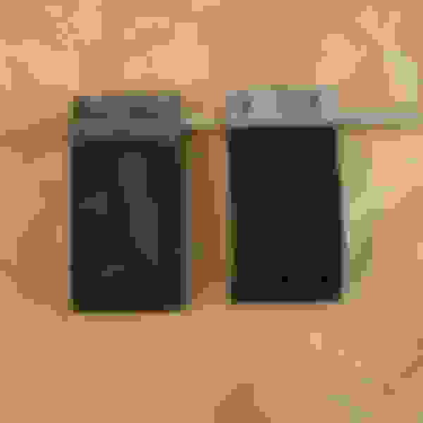
Well, the new driveshaft from Denny's Driveshafts arrived on Friday, finally had time to install it this afternoon and the rear u-joint is not correct and will not fit the pinion yoke. More replacement parts that don't work! It sure is pretty though.
Found this on my front step.
Laid side by side with the stock driveshaft. At first glance I thought it was too short because the distance between the u-joints was shorter than the stock one, but on closer inspection, the slip yoke is longer
Unfortunately, the new driveshaft has the wrong u-joint in the rear. At 2.64 inches, the distance across the snap rings is too large to fit the pinion yoke.
I got the driveshaft sorted out. Denny's driveshafts installed a Dodge u-joint (Spicer 539) at the pinion end of the shaft; the correct Spicer part number for a 1330 to GM 3R is 793. To remedy the mistake, Denny's sent me 3R replacement caps to swap out for the Dodge caps. It turns out Spicer uses the same cross frame for their u-joints so I only needed to swap out the caps. At 3.5" in diameter, the new driveshaft is bigger than stock and it interferes with the parking brake cable so another modification will be necessary.
After getting the dash installed I focused on the gauge wiring and bezel mods. The SpeedHut gauges look awesome; the quad gauge has fuel, oil, temp & volt meters. Each gauge has a programmable alert light but it lacks some of the factory indicators, most notably no brake light, so I added a small, LED parking brake indicator between the quad gauge and the speedo. I also wanted to be able to monitor the temp of the transmission, so I wired in a switching relay and added a small, momentary pushbutton to the gauge bezel. The relay will let the temp gauge normally read the engine temp, when the button is pushed the gauge will read the trans temp.
One downside of the SpeedHut gauges, they didn't allow enough space for the factory courtesy lights above the wiper switch and heater control. I fab'd up some thinner alternatives using LED strips mounted to aluminum plates, but the SpeedHut back lighting is more blue than the factory diffusers which are more of a teal color. I bought some peal-and-stick blue tint film online to cover the back side of the factory diffusor lenses, cut paper templates to fit the diffusors then transferred them to the film.
Here's some pics.
Rodney
The SpeedHut gauges use threaded mounting rings to hold them in place.
I mounted them in a steel plate and transferred the mounting holes from the dash.
Bought this blue film online to make the dash difussors more blue and less teal.
I applied the peal and stick film to the back side of the difussors to darken the blue dash light.
This is the switching relay for the temp gauge; it's mounted to the steering column support behind the speedo. The gauge reads engine temp until the button is pushed then it will read the trans temp.
I drilled out the gauge bezel and epoxied a micro push-button switch to control the temp relay.
The little red button is barely visible.
The finished product. I don't really like the zebra striped appearance on the heat controls, caused by the individual LEDs on the lighting strip.
Last edited by cdrod; December 10th, 2023 at 03:03 AM.
I got the driveshaft sorted out. Denny's driveshafts installed a Dodge u-joint (Spicer 539) at the pinion end of the shaft; the correct Spicer part number for a 1330 to GM 3R is 793. To remedy the mistake, Denny's sent me 3R replacement caps to swap out for the Dodge caps. It turns out Spicer uses the same cross frame for their u-joints so I only needed to swap out the caps. At 3.5" in diameter, the new driveshaft is bigger than stock and it interferes with the parking brake cable so another modification will be necessary.
After getting the dash installed I focused on the gauge wiring and bezel mods. The SpeedHut gauges look awesome; the quad gauge has fuel, oil, temp & volt meters. Each gauge has a programmable alert light but it lacks some of the factory indicators, most notably no brake light, so I added a small, LED parking brake indicator between the quad gauge and the speedo. I also wanted to be able to monitor the temp of the transmission, so I wired in a switching relay and added a small, momentary pushbutton to the gauge bezel. The relay will let the temp gauge normally read the engine temp, when the button is pushed the gauge will read the trans temp.
One downside of the SpeedHut gauges, they didn't allow enough space for the factory courtesy lights above the wiper switch and heater control. I fab'd up some thinner alternatives using LED strips mounted to aluminum plates, but the SpeedHut back lighting is more blue than the factory diffusers which are more of a teal color. I bought some peal-and-stick blue tint film online to cover the back side of the factory diffusor lenses, cut paper templates to fit the diffusors then transferred them to the film.
Here's some pics.
Rodney
The SpeedHut gauges use threaded mounting rings to hold them in place.
I mounted them in a steel plate and transferred the mounting holes from the dash.
Bought this blue film online to make the dash difussors more blue and less teal.
I applied the peal and stick film to the back side of the difussors to darken the blue dash light.
This is the switching relay for the temp gauge; it's mounted to the steering column support behind the speedo. The gauge reads engine temp until the button is pushed then it will read the trans temp.
I drilled out the gauge bezel and epoxied a micro push-button switch to control the temp relay.
The little red button is barely visible.
The finished product. I don't really like the zebra striped appearance on the heat controls, caused by the individual LEDs on the lighting strip.
The gauges are SpeedHut's 4-1/2" models: GR4.5-Quad, GR4.5-Speedo, & GL4.5-Tach. The stock, 3-hole gauge bezel fit inside the diameter of the SpeedHut gauge but was too deep to fully seat into the dash. To remedy the tight fit, I carefully trimmed the backside of the stock gauge bezel using a Dremel tool and closely measured the thickness with a set of calipers. I had SpeedHut design custom faceplates to mimic the stock Olds lettering and spacing. It was a tedious process but I'm very satisfied with the final results.
Rodney
Last edited by cdrod; December 23rd, 2023 at 09:31 PM.
Time to update this thread. I've been in gremlin hell for the past month or two. The emergency brake light indicator in the dash stays on all the time; since I have aftermarket gauges which don't have a parking brake light, I found the emergency brake wire in the dash harness and wired in an LED indicator with a big "P". The problem seems to be with the combo/distribution valve on the frame rail. I installed all new brake lines including this distribution valve; it seems this is a fairly common issue when bleeding the brakes for the first time after installing new lines. I pressure bled the system and I think I pushed the switch too far. I'm going to try to recenter the switch in the valve - wish me luck on this one.
The next gremlin to tackle was the non-working speedometer. Again, the aftermarket gauges I installed are electronic and require a speed sender which wasn't sending the proper pulses to the speedometer. A new sender fixed this problem, but not before tearing into the harness to confirm correct wiring. Always fun to solder connectors lying on your back, underneath your car! To troubleshoot the speedo problem I put the car up on jacks stands so I could test in the garage. This presented another unknown wiring bug. I have a TH200-4r transmission with a lock-up convertor wired to a 4th gear pressure switch; this way the convertor would lock-up anytime the transmission is in 4the gear (OD). The torque convertor lock-up circuit wasn't wired correctly so the convertor would stay locked-up and stall the engine as I slowed down the freewheeling rear tires. Conceptually, this should have been an easy fix, but digging into the wiring harness to correct it was fairly involved. I ended up redesigning the entire lock-up circuit to fix the wiring problem and added a vacuum switch and a time delay relay. To prevent the convertor from going in and out of lockup too quickly "i.e. hunting", I added a Beuler BU510TD time delay relay to delay lock up for 8 seconds after the brakes are applied or the vacuum drops from stepping on the gas. This should provided for better "manners" when the convertor unlocks in traffic or when passing.
Next problem; parking brake not tight enough. In Texas, we have mandatory safety inspections when registering the vehicle; gotta have a working parking brake. A secondary issue with the parking brake was the intermediate cable was rubbing on my new 3.5" driveshaft. The factory driveshaft was the 2-piece variety with a rubber insert between the 2 sections. I guess Olds did this to minimize NVH from the differential. The stock driveshaft also necked down at the transmission, where my new driveshaft is a full 3.5" from pinion to transmission. These 2 issues were resolved with a $45 parking brake cable kit bought on Amazon, a new front cable from Rock Auto and new cable routing. The new cables are routed along the LH (drivers) side of the car, with the RH cable attached to the tunnel brace to safely pass over the driveshaft. The Amazon cable kit is the same as the much more expensive Lokar & Wilwood kits without the branding; very nice set-up. I needed a longer front cable because of the re-routing. After a little RockAuto research I discovered the X-body cars (Nova, Omega, etc.) have the same cable attachment at the cowl and the parking brake pedal with a longer, sheathed cable. I drilled out the transmission cross member to secure the front cable and mounted the a bracket for the 2 rear cables on one of the floor braces. Works really well and no more rubbing on the driveshaft.
Next problem; windshield wipers won't park. I bought a new wiper motor and washer pump from Lectric Limited which worked as expected but the washer pump was not working. After consulting the CO braintrust, It was recommended to purchase an electric washer module from Trico to substitute for the mechanical, Rube Goldberg contraption that is the stock washer pump. After making the swap, the washer problem was solved, but then the wiper motor became tempermental and would not always park right away making a few extra passes before finally parking properly. Eventually, the wipers wouldn't park at all. I pulled the motor to bench test the problem and of course the problem disappeared. Mounted back on the car, wipers won't park. I called Lectric Limited and spoke with a service person who told me to follow the special "set-up procedure" for new wiper motors. I asked if this was in the Fisher Body manual, he confirmed it was in the book. There is no such set-up procedure in the Fisher book! I'm going to try to send the motor back to Lectric, but I think I'm in for a fight on this one. Tired of jacking around with brand new parts that don't work, I pulled a old motor from my stash of spare parts and found one in working condition. I cleaned the contacts, lubrication the gears, etc. works great! After reinstalling on the car I realized it's clocked differently than the stock Olds motor, it appears to be for an F-body (Camaro, FIrebird) but it works so it's staying on the car for now.
Next up for this weekend; replace a blown headlight bulb, investigate the steering wheel clocking (45-degree off-center), finish plumbing the PCV valve and my home made catch can.
Here's some pics of the parking brake set-up:
Rodney
The front cable is for a mid 70's Nova and was just long enough to reach the transmission cross member. I drilled a 9/16" hole to support the front cable housing. The two cables at the top of the photo travel to each rear wheel.
The parking brake travel was too short and the emergency brake pedal under the dash would only move 1-2 clicks before locking up. I added the spring between the front cable and the equalizer block to allow the dash pedal to travel further before getting tight.
Caliper connection.
Last edited by cdrod; March 30th, 2024 at 12:51 PM.
After reworking the parking brake cables I was still having a difficult time getting the RH wheel to hold tightly. I was still using the old pads and rotors that came off the used '01 Blazer; I figured at the time, no sense in buying all new parts until I was satisfied with the custom installation. Upon closer inspection, the old pads were pretty worn, as were the parking brake shoes; but more importantly, the paint on the pads was wrinkled likely from brake fluid leaking past the caliper seals and the parking brake shoes looked like they has absorbed some of this leaking fluid. I decided to order new parts to eliminate these variables in my troubleshooting; new pads, rotors and parking brake shoes have arrived from Amazon, and Rock Auto.
While messing around with the rear brakes, I decided to revisit a problem that I had encountered earlier in the build process. The rear axles had significant endplay; approximately 0.036"- 0.039". Jim (Monzaz on CO) from JD Race & Restoration who builds rear ends for a living says 0.010 or less is the desired target range. The looseness was entirely in the tapered wheel bearing; no amount of spacers or tightening would reduce the endplay. I had bought new Timken bearings from Jim back in 2014 when I rebuilt the rear end, but decided to try another brand in search of tighter end-play and purchased National branded parts.
I was happy to find the internal play in the National bearing was only 0.013" so I was off to the machine shop to press on the new bearings & seals. Unfortunately, the shop incorrectly pressed the bearings onto the axles pressing on the outer race which damaged the bearings. I'm trying to reach the machine shop owner (who is frequently not at his shop) to discuss the damage; in the mean time I've ordered replacement parts which hopefully will arrive today. I'd like to get the bearings pressed on (correctly this time) before the end of the week so I can reassemble the car on Saturday. Here's some pics of the problems.
Rodney
This is the damaged outer wheel bearing race. If you look closely you can see small nicks caused by excessive pressure on the rollers. The shop should have pressed against the inner race (not the outer race) when pressing them on to the axles which would have avoided this damage.
These are the A9 bearings from National. All replacement bearings are a tapered style where the original bearings for BOP rear ends previously used a cylinder type roller which was much less sensitive to the end play issues I'm currently fighting.
The tapered bearings must be installed in the correct direction. The outer groove goes to the wheel side of the axle which orients the taper toward the pumpkin.
Last edited by cdrod; April 23rd, 2024 at 05:47 AM.
Fuggin idiots. Hard to find people who can think and stand up at the same time. You would think just by looking at the assembly they would be able to figure this was NOT the way to press the bearings on and it would result in damage.
I ordered replacement bearings and will take everything back to the machine shop tomorrow to do it again. I couldn't get two National bearings quickly, so I took a chance on the SKF brand. I was pleasantly surprise to find these were made in Japan where the National branded bearings came from China. I measured the internal play of the SKF bearings and found them to be exactly .010"; this should take care of the endplay problems I was having. Hopefully the machine shop will expedite this for me so I can reassemble the car this weekend.
SKF is also generally high quality. I can't recall - I think National is the market leader in tapered in SKF is the leader in roller? Something like that. And by "leader" I mean the company that does the R&D and generally regarded as highest quality.
I've seen similar where National seems a bit hit and miss. they're probably getting these older low-volume things from other suppliers now.
 June 28th, 2023, 12:33 AM