When you click on links to various merchants on this site and make a purchase, this can result in this site earning a commission. Affiliate programs and affiliations include, but are not limited to, the eBay Partner Network.
I have received some feedback from some of our forum members here that they were not aware of the existence of the camshaft thrust plates I have been producing for the '64-'90 Oldsmobile Gen II engines as they have only been "lost in the sea" of parts for sale listings of the ClassicOldsmobile forum and Ebay. I have all of these engines covered now, including the new 403 only thrust plate design. As I am building a 540 cube Rocket Racing block based twin TorqStorm supercharged engine, I will be engineering a specific camshaft thrust plate for this engine block design also, as I am not going to run without one! I will say that due to the re-arranged positions of the oil gallery plugs on this Rocket block that it is going to take some creative engineering to design the plate for this application. I will be trying to stay away from requiring any additional machining to the engine block to accommodate, though it does initially appear that the design *might* require one or two additional holes be drilled and tapped into the face of the Rocket Racing engine block to properly secure this plate - maybe not. I would highly prefer to develop a plate that is indeed a direct bolt in - it may be possible, but time and testing will tell. The good news is that all of the conventional '64-'90 Gen II Olds engines can enjoy a direct bolt of these plates with zero modifications required.
Here is the standard Gen II plate:
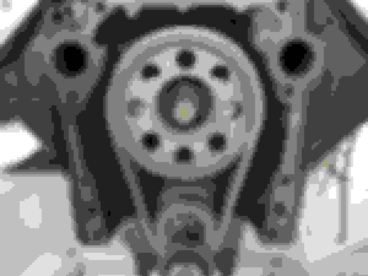
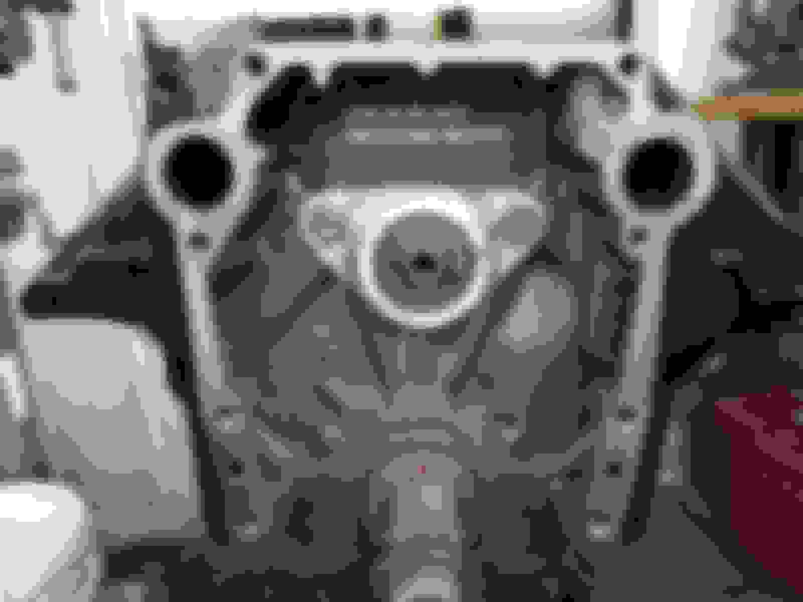
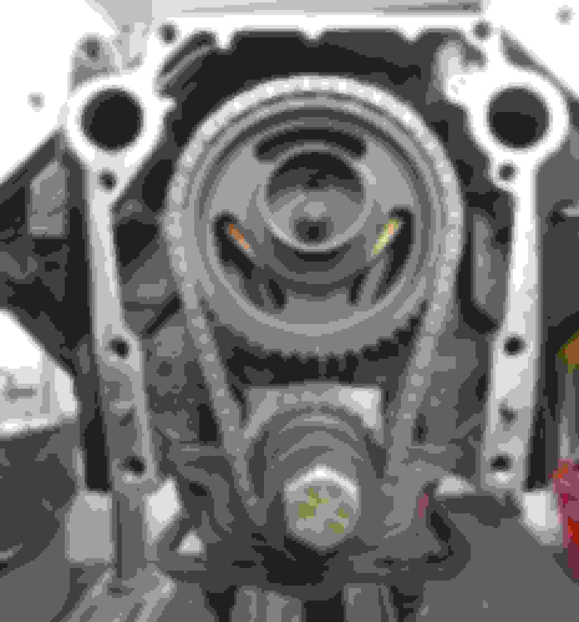
This item is beautifully CNC machined out of a billet C93200 Bearing Grade Bronze - twice as tough as the original GM mild steel plate was when I Rockwell tested it for hardness. This is the backside of the plate that mounts to the engine block and controls the forward most end of the camshafts front timing chain gear mounting flange. Here is the plate installed using the standard factory oil gallery plugs. I have designed this plate to specifically use the original oil gallery plugs. There is no need to scavenge around for any possibly longer plugs. Here is the plate installed behind a Cloyes double roller timing chain set. What's interesting in this image is that I have also installed a typical camshaft thrust button that most everybody is accustomed to for visual reference. While you can also run this old school camshaft thrust button in conjunction with the camshaft thrust plate, there is no reason for it at all and I actually recommend against using the thrust button.
And now here below is the newly designed and fully tested 403 only thrust plate design:
Here is the original handmade prototype 403 plate. I took the original design at the bottom of the picture, cut it all up, then silver soldered it all back together in the revised pattern needed to create a master plate. All of the tooling used to cut up and reconfigure the 403 only plate design. It took a few days, but I finally nailed it just right. Here is the prototype master plate test fit, making certain that it centers properly across the face of the camshaft, the oil gallery plugs, and provided the exacting amount of camshaft thrust end play. With the 403 having the revised oil gallery plug locations raised up higher, I was very pleased to see that everything still cleared every type of timing chain tested. Here is the finished design installed. The master plate was CNC patterned, machined, and test fit perfectly!
Final finished design testing behind different timing chain sets to ensure proper clearances all proved out perfectly.
The genesis of this plate design has been documented in a different section of this forum - you can jump over to this discussion and read all about it:
Summary? These are now currently available either through the Ebay listing OR you can enjoy a discounted exclusive pricing as a ClassicOldsmobile member by sending me a private message including your name, e-mail address, your ship to address, along with a good daytime telephone number. Once all of the information is in place in the private message, I will send you a PayPal invoice for payment (you can pay a variety of different ways without having to be a PayPal member). I have been carrying a good stock on these plates now as they have become popular enough for me to have the machinists run these plates in larger batches for me more often now. Unless it comes to pass that I am caught out of stock at some random point in the future, I typically ship these within 24-48 hours using UPS Ground, providing tracking at the time of shipment.
Let me know if you may have any questions. And yes, while these are mandatory to properly install a roller cam retrofit into your Olds, they are also fantastic for use on standard flat tappet cam installations too.
ask any cam manufacturer what min max is and they�ll say around 3 to 10, or less in the max
ive always set about .005�
I have tested these cam thrust plates on a variety of different blocks, finding them to go as tight as .001" to as loose as .015" in block to block to block variations. As such, I am advertising the loose end of the spectrum. If you read through my description thoroughly, you will find that I mention that I have made these plates .060" thicker than needed, to where a discerning builder could machine the backside of the plate down as needed to adjust thrust end play as desired.
You state that you run at .005" clearance. I am assuming this is a thrust button clearance you are speaking of? If so, are you running a stock .120" thick timing cover? If you are running the stock thin timing cover, you may not be aware that the water pump builds a LOT of pressure at high RPM's ballooning the stock timing cover inwards towards the cam thrust button, now shoving the cam inward against the engine block potentially bringing premature wear of the engine block's thrust surface (!), especially if you are also running a high-volume water pump. If you are running an electric water pump or a Rocket Racing billet aluminum timing cover, then yes, you can count on that cam thrust end play to essentially stay put during a pass.
Again, I can't stress enough that the stock Olds timing cover is thin, very thin at .120" and will balloon inward towards the cam during a high RPM blast as the timing cover in the Olds design essentially acts as the backside of the water pump. That is why the factory Olds cam bolt has the elongated blank stud area sticking out quite a ways out forward past the six-point hex mounting area, as they knew the timing covers ballooned inward (why else would they have bothered to have this longer blank shank area as part of their cam bolt design?). Think about it - things that make you go hmmm...
Paul...
no, they don�t balloon inward. I�ve got a big block Olds powered jet boat that I had cooling system spikes of 30 to 50 psi before I found the problem
it didn�t drive the cam into the block or hurt the thrust bumper.
I�ve pulled apart my own race engine after hundreds of runs and the thrust clearance was the same as it was set at when built
Last edited by CANADIANOLDS; May 18th, 2023 at 06:17 PM.
no, they don�t balloon inward. I�ve got a big block Olds powered jet boat that I had cooling system spikes of 30 to 50 psi before I found the problem
it didn�t drive the cam into the block or hurt the thrust bumper.
I�ve pulled apart my own race engine after hundreds of runs and the thrust clearance was the same as it was set at when built
Having a jet boat means that you are not using a conventional water pump, instead circulating water through the engine with one of these plates:
Jet boat water inlet - not a conventional water pump. Water is brought in by the jet pump instead of an impeller circulating coolant as you would find in an automotive application.
Your jet boat may have had some 30-50 PSI pressure spikes as you were bouncing around across the waves - I can easily picture that. Now your race engine also likely has a considerably under driven pulley arrangement providing it is running a conventional impeller style automotive water pump. Or is it running a pump with the impellers trimmed down to reduce parasitic losses? (old racers trick) Or might you be running an electric water pump? I have bored a hole into the main body of an Olds water pump so that I could connect a pressure gauge into the water pump to measure what is going on right inside of the water pump. A popular replacement water pump is an air conditioning spec high volume water pump. There also isn't much choice in pulleys for the Olds save for hunting down the early model pulleys. The aftermarket pulleys I have seen spin the water pumps at late model pulley speeds. As you will see in the W30 and W31 and some other earlier model Olds engines, the water pump pulleys are quite large as compared to the smaller sized crank pulleys. The Olds engineers knew they had to slow down the water pumps on their high performance models to prevent water pump ballooning and cavitation. With later model pulleys, the water pump speeds are very high. The average 7 3/4" crank pulley versus the typical 5 1/2" water pump pulley means that the impeller speed is 1.4 times faster than the crankshaft speed. 6000 RPM of crank speed = a whopping 8400 RPM water pump impeller speed. Rev that engine to 6500, and now your impeller speed is 9100 RPM (doh!). This creates a LOT of pressure at the backside of the water pump, which happens to be the timing cover. In the aforementioned water pump where I drilled and tapped into it to measure the pressure, I was seeing readings of over a 150 PSI at max impeller speeds. A 150 PSI against a .120" thin sheet metal timing cover IS ballooning inward. If you haven't seen any wear on your end, that's great, likely a testimony to how good the oil is that you use.
All I am saying is that the Oldsmobile engineers looked long and hard at the best way to handle camshaft thrust end play, having millions of dollars worth of research into their development. They came to the conclusion that a camshaft thrust plate was the best answer for controlling their upgrade to the roller cams in the last version of the Olds Gen II V8 engine instead of a potentially inaccurate thrust button design. This cam thrust plate is not my idea - my version is a redesign of the now extinct factory original Oldsmobile design. I tightened up the average thrust end play, loosened up the hole sizes where the oil gallery plugs mount it to the engine block so that it could be centered best as needed, thickened up the plate to strengthen it and allow for enough extra meat on the backside to allow it to be custom milled if needed, then produced it out of a superior bearing grade bronze alloy.
Summary? Aftermarket camshaft thrust buttons have been in use on the Oldsmobile engines well before many readers here were even born. I have observed that stock timing covers can balloon inward under high RPM's. I specifically use low volume non A/C late model water pumps on all of my high winding builds to prevent excessive water pump pressures. High flowing water pumps do NOT help cooling - that is a function of the BTU rejection rate of the radiator.
Again, there are people who have experienced differing results in their builds, and therefore develop different opinions about what makes things tick. I am not here to debate what some believe, only working with my own observations and testing. Anybody reading this can come to their own conclusions. The good news is that we are discussing topics that are rarely touched upon, which makes for great conversation and educational reading. No way do I want to get into any adversarial positions in these discussions - please do not read this as such, as everybody's "mileage may vary"
Paul...
you�re a great story teller, I�ll give you that much.
my jet boat uses the conventional water pump..it�s a Berkeley packajet.
you are full of bs saying you seen 150 psi in the water pump area. Water pumps do not pump, they circulate. Being an engineer I thought you would know that? They do not make pressure, the circulate water, that�s it.
It�s a closed system where the pressure is the same throughout the system, a liquid can�t be compressed.
the timing cover is more that sturdy enough to take any cam walk forward�the water pump itself also adds to the rigidity because it has two bolts that clamp it about an inch below the cam centerline.
you found a solution to a problem that doesn�t exist 😁
Beekeley packajet
Last edited by CANADIANOLDS; May 19th, 2023 at 06:52 AM.
First, a water pump IS a vane pump. They are called water pumps, not circulators for a reason - the english is rather clear on this. Being a mechanically driven impeller trapped inside of a specifically contoured body, they are subject to the RPM's that the impeller spins. They are designed to PUMP enough volume at idle to circulate coolant at an adequate rate. Anybody that has looked inside of a radiator as you are filling it, sees when the thermostat opens - a vastly larger amount of coolant starts flowing of course. Now mind you, this is simply just at idle / off idle. With the thermostat completely open, raising the engine RPM's results in an increase in flow obviously visual as you look into the radiator. So, ok, all of the above is average everyday knowledge that most have observed many times. Now let's document some basic measurements for use in this discussion:
* 1.650" Water pump inlet inner diameter / suction (where the lower radiator hose connects to the pump)
* 1.115" Timing cover coolant pass through holes x 2 (one on each side of the timing cover)
* 1.045" Thermostat pass through OD
For the sake of discussion, have you ever run an engine with the thermostat removed? Most have tried this at one point or another. If so, then you have observed wild circulation of the coolant inside of the radiator, usually so much so that it is splashing out of the radiator cap seat at idle / off idle speeds. That level of uncontrolled flow is actually quite dangerous, as it is completely unregulated and can pop an upper radiator hose or the radiator itself at higher RPM's. This is why restrictors of various hole sizes are used in place of a thermostat so as to keep the water pump from going berserk, pumping this excessive pressure on the output side of the cooling system. If your water pump inlet port is 1.650", and your thermostat wide open is 1.045" (of effective open diameter when hot), then you realize that the thermostat is a flow regulator keeping the water pump essentially in check.
Next, some may have found this out the hard way, but a heater core cannot be connected to just a simple hose nipple with a large inner diameter in it to your intake manifold output port. Of course it will flow coolant, but go make a high RPM pass and you may build so much pressure in your heater core that it will pop, filling your car up with greasy antifreeze steam (no fun - coats your entire interior with antifreeze slime). The factory heater hose nipples / heater control valves had an orifice inside of them of approximately .200" to limit how much flow could be put to your heater core.
How much pressure do you think it would take to blow a healthy radiator or heater core apart? Or a brand-new heater or radiator hose into failure? Let's just suffice to say it is at very least 60 -75 PSI.
I had built a very high winding 350 many years ago, spinning it to 7200 RPM. This thing kept blowing water pump gaskets, driving me nuts. I ***** punched all of the gasket surfaces every 1/8" on the timing cover and the water pump so as to physically bite down on the gasket. Well, that seemed to have worked for a while and then POP, there it went again. After throwing every cuss word in my arsenal at it, I replaced the water pump and the timing cover with Genuine GM over the counter dealership parts that were still available back in the '80's. I noticed the timing cover had embossed areas in between certain parts that were obviously there to help increase the clamp load on the gasket. I thought to myself AHA, I must've ground these down using the air motor to clean off the gasket surfaces. Just to be sure, I ***** punched all of the surfaces again on the brand new timing cover and water pump, also applying Permatex aviation sealant, torquing everything down perfectly and sequentially a few times over the course of an hour. When I could finally no longer achieve any further movement of the bolts without risking shearing them off, I let it all sit overnight to fully dry. The next day, I filled it with antifreeze, burped out all of the air, and thought to myself "I've got you now, you SOB". All was well for the week, then out on Gratiot Avenue racing Saturday night IT DID IT AGAIN at 7200 RPM. I was just beside myself. So of course, now I'm obsessed with finding out what in the absolute hell is going on. I painstakingly dug the water pump back out, muttering about how every damn bracket seemed to just have to be connected to this dag blasted water pump - sigh... I used carburetor cleaner spray and a gentle hand held wire brush to remove all of the glued down gasket residue so as not to remove how sharp the ***** punch marks were along with the factory embossments in the timing cover. As you can imagine, I was just perplexed as to what was causing me all of this heart ache and hassle. I drove down to D & S Engines in Clawson to talk to my machinist guru Doug about what I was experiencing. He didn't have anything to particularly offer at that point, stating that I should try a different brand of gasket and use a different sealant as I was apparently building too much pump pressure at high RPM's. So, I did, and as you can surmise it did it again. Now this time I had to take some action to see what in the world was causing me all of this grief. I drilled a hole into the driver's side of the water pump right above where the power steering pump bracket mounted so that I could grab my transmission pressure test gauge and read what pressures were building up in there to be causing these repeated high RPM gasket blow outs. At high idle, I was barely showing any pressure on the gauge. The upper radiator hose was rock solid, so I knew I had all of the air burped out of the cooling system properly. As I started revving up the engine, here we go - pressures building! Now I've caught this thing with its hand in the cookie jar! Being a trans test gauge, it had a nice long hose on it with a large dial face that I duct taped to my windshield. I took the car out on the road, finding that common road speeds were only in the area of 50-60 PSI, which had me scratching my head as the radiator cap was an 18 lb setting. Ok, so the water pump impeller actions must be building pressure right here inside of the water pump. Now I have to see what happens when I stand on it real good. OMG! At 7200 RPM, I am seeing a 150 +/- on the gauge! No wonder this thing is popping gaskets...
NOTE: MY ORIGINAL POST CAME UP WITH A NOTICE THAT IT WAS TOO LONG, SO I AM BREAKING THIS UP INTO PART 1 AND PART 2
Last edited by Clark455; May 19th, 2023 at 08:46 PM.
Sooooo.... after talking to a bunch of acquaintances that I raced with back then (before the wonderful world library of the internet), a Pontiac racer said he had similar problems until he trimmed the blades of his water pump impeller down. Excited to see if this would fix my problem, I got to work on it, worried about possibly imbalancing the impeller. I rigged it up to an electric motor spinning at 3450 RPM, playing around with taking off a little metal here and there methodically until I could feel no more particular imbalance. Great! Let's get this back together and see what happens. YEP - gauge readings dropped WAY down from 150 to about 60 PSI at 7200 RPM. Hooray - no more blown water pump gaskets! This was not an A/C car, so it did OK on the hot muggy Michigan days stuck in bumper to bumper traffic, but did heat up some so I got used to popping it into neutral and raising the RPM's up watching the temp slowly come back down - fan clutch operating properly, fan shroud in place. This did start getting on my nerves a bit, thinking I had cut off too much of my impeller in the pump. I ran this way for quite a while, and it was what it was, as I was just tired of digging the water pump out. A few weeks later, I was talking about this at the Saturday night parking lot gathering at our spot on good ol' Gratiot avenue. I then ran into a guy that had the answer for me - I couldn't believe it. He told me to go get a stock replacement lower flowing NON A/C water pump, and he was going to hook me up with a milk crate he had of all different sizes and styles of Oldsmobile pulleys. Well, digging around in the collection of pulleys, I found a much larger water pump pulley and then a correlating smaller crank pulley. I went to town installing the non A/C water pump, the different diameter pulleys, and then thought about drilling and tapping another hole in this new water pump to see what the readings would be. I did, as I figured I could then just install a 1/8 NPT pipe plug in the casting when I was done. Sure enough, gauge readings were WAY down at 7200, in the area of 40-45 PSI - yes yes yes - nailed it, never had a problem again of any sort, cooling system stable as a table from there on out.
Over the next few years, that water pump fiasco haunted me with every Olds I had tangled with from there on out. Working with thrust buttons back then, yanking cams in and out of various customer cars, I started noticing some had accelerated wear on the front of the block in the camshaft thrust surface area along with a prominent witness mark on the inside of the timing cover (where the front of the thrust button could contact). I studied the timing covers using a straight edge, finding that anytime there was a job that had heavier wear in the front of the block that it was also found to have the inward depression of the timing cover along the backside of where the water pump was - the crown being just about exactly on center with the location of the cam's thrust button. Hmmm - so I started replacing any timing covers that showed this dip / depression, swapping out the water pumps for the lower flowing non A/C water pumps. I had not built many other higher winding Olds engines, but the ones that I did got that hole drilled into the water pump and checked with my trans pressure gauge. If I found one that was approaching 90-100 PSI at 5800, I'd found that I knew at that point exactly how much metal to take off of the water pump's impeller to lower the pressure down, as locating the different pulleys I had was nay impossible. I realized later that I had apparently scored some W31 pulleys, as I recognized them at a car show one day - no wonder they were so hard to try to find.
Now if I haven't completely worn you out yet from reading, (I'm worn out from writing at this point!), the moral of my story is that I DID indeed find excessive water pump / block pressures occurring on the driver's side of both the small and big block Olds engines I had worked with. I never did bother to drill / tap / test anywhere else in the water pumps, as it seems that I just got lucky finding the right spot on the first go. Maybe the other points are also prone to these high pressure rises? Dunno, probably... Finding the bowed inward timing covers seemed like a long gone problem until 25 some odd years later as I had not built another high winding Olds since. I built a 488 stroker about 5-6 years ago, installed a Classic Industries brand new timing cover, my favorite lower flow non A/C water pump, and SON OF A B*TCH if it didn't pull the same damned thing with me again. Back chasing it with everything I know now, and comparing notes with others out there building Olds engines, it turns out that these new reproduction timing covers flooding the market now are of a lesser strength than the original covers are, AND they don't have the stamped in embossments that help to secure the water pump gasket better. I only use the CNC machined billet aluminum Rocket Racing timing covers now which have enough rigidity to provide ZERO deflection under any circumstance.
Now here's something interesting - a late model Chevy LS thermostat with a special additional block pressure blow off valve built into the bottom of it: Look at the bottom of this T-stat. See the large spring-loaded disc? This is a block pressure blow off valve. Interesting, no?
Now let's go back into the measurement end of the discussion. If you have a large inlet into the water pump, considerably sized output ports that feed into the engine block, where does all of the pressure go at higher RPM's if the thermostat is not fully open? Studying the Chevy LS design, it appears as though they have set it up to blow off excessive pressure by recirculating the coolant and then blowing some off in flow through the radiator despite the 'stat not being open at such time. I knew there seemed to be a high RPM problem with the earlier 20th century engines, but they were never really wound to speeds high enough to manifest a chronic problem. Seeing this type of over pressure blow off design thermostat almost everywhere nowadays tells me I was barking up the right tree all along, and now all of these years later, IT'S FIXED!
Again, your mileage may vary, but I have experienced timing covers that have been bowed inward every so slightly right behind the center of the water impeller (especially if it is weakened by the typical corrosion you usually find in the front side of the timing cover). If you can catch it with a straight edge once removed from the engine, then you know it was certainly ballooning inward further while it was still in the engine.
Others not finding this or generally not agreeing does not disprove what I went through. It really ran me through the ringer back in the day, then reared its ugly head again with the cheesy aftermarket reproduction timing covers out on the market now with that "OH NO YOU DONT - NOT AGAIN" scenario of blowing another water pump gasket AGAIN on the 488 (that really frosted me).
Anyway, I hope this helps, even if it is only one person out there!
While making some "highly spirited" runs yesterday, I revved the engine further than I have ever and oh snap - antifreeze everywhere - uh oh!
Doh! Never had this happen before - first time for everything!
I am only running a 13 PSI radiator cap, so here is testimony to how much internal block pressure a water pump can produce at high RPM's. I was VERY relieved to see that this is all that happened, but oh my gosh, my entire engine compartment and the entire underbody of my car have now been thoroughly slimed with antifreeze. Replacing the T stat housing only took 5 minutes, but it is going to take who knows how long to clean up the rest of the mess all of that antifreeze made. Air filter element in the garbagio, and green gook everywhere you can think of, even dripping off of the rear bumper. This happened at about a 160 MPH, so the wind snatched it up and slimed it backwards all the way onto the outside of my rear window and trunk. I also had my windows down, so my interior also got a misting of this slimy goo too along with the taste in my mouth and a misting onto my glasses - YUCK
I have used this exact thermostat housing for years on a few different engines, so it has been a tried and true time tested part. Having this happen just recently after having posted about internal block pressures produced by a water pump at high RPM's will be funny someday looking back at this, but I have a hellacious mess underhood, topside, and bottomside to clean up now - sigh...
I am going to contact CVF Racing and see if they can custom make a water pump pulley for my front accessory drive 1" larger in diameter to slow the water pump down a bit. If not, the water pump is coming out and getting its impeller fins cut down to ease up on the block pressures developing at high RPM. There is plenty of coolant flow at idle, so cutting back on what the water pump is doing at high rev's is going to have to dealt with - again, either via slowing the pump down with a larger diameter pulley, or trimming the vanes inside of the pump...
I suppose I need to be living proof of these things happening, right? I AM glad that this is all that happened though (!)
I spent the first forty years of my life living right across the Detroit River from Canadians. Most were civil, nice people, though some of you simply should've been stopped at the border...
Hey, Dale, I've got an idea! Try something new - it may take some effort from what I have seen of you, but be nice would ya? Try it - as it just might work (or maybe you are just too far gone).
Oldsmobile owners are the classy suit and tie civilized guys. Somewhere along the line you got hung up on the word exotic and have been poking it at me in your childish little digs and jabs here and there. What was it, my engine listing? Whatever your problem is, feel free to disagree with me if you wish, but let's at least work with some common decency, no?
de�cen�cy
[ˈdēsənsē]
NOUN
behavior that conforms to accepted standards of morality or respectability
Paul
Last edited by Clark455; May 24th, 2023 at 04:41 AM.
Here is a quote out of this discussion by a gentleman's screen name of Tuner:
"The ‘ah-ha moment’ was in understanding that the OE type engine driven pumps pressurize the system several lbs. per 1000 RPM. I recall 10lbs per 1000RPM when the pump is 1 to 1 with the crank, but that seems like a lot, it’s been a long time since I read the information. Put a pressure gauge on your cooling system and see."
Now with the average later model Olds crank pulley diameter of 7 3/4" versus the typical 5 1/2" water pump pulley, this means that the impeller speed is 1.4 times faster than the crankshaft speed. 6000 RPM of crank speed = a whopping 8400 RPM water pump impeller speed. Rev that engine to 6500, and now your impeller speed is 9100 RPM (doh!). This creates a LOT of pressure. So if "Tuner" from Don Terrill's Speed-Talk is speaking of 10 lbs per 1000 RPM with a 1:1 crank to water pump pulley ratio, that's 60 PSI at 6000 RPM. Now if we take and change the math to the Olds ratio of 1.4:1 water pump pulley ratio that comes to 84 PSI, as the impeller speed is 8400 RPM. At 6500 RPM, this equates to an impeller speed of 9100 RPM. Using the math as presented by "Tuner" in the Speed-Talk discussion, this comes to over 90 PSI of block pressure. What I measured in my testing of boring a hole into the water pump, threading it, and connecting up a trans pressure test gauge was water pump internal pressure right at the edge of the impeller.
Here is another discussion of very high block pressures: Speed-Talk Discussion
"I put a pressure gauge on the heater hose coming from the intake manifold. Water pressure was around nothing at idle, and it would ramp up to over 120psi over 3500rpm or so. I did not dare check higher."
 May 10th, 2023, 09:33 AM


")


