General Discussion Discuss your Oldsmobile or other car-related topics.

external voltage regulator capacitor wire routing

Thread Tools
 
Search this Thread
 
Old January 23rd, 2022, 07:06 AM
  #1  
Registered User
Thread Starter
 
Warren Seale's Avatar
 
Join Date: Aug 2013
Posts: 136
external voltage regulator capacitor wire routing

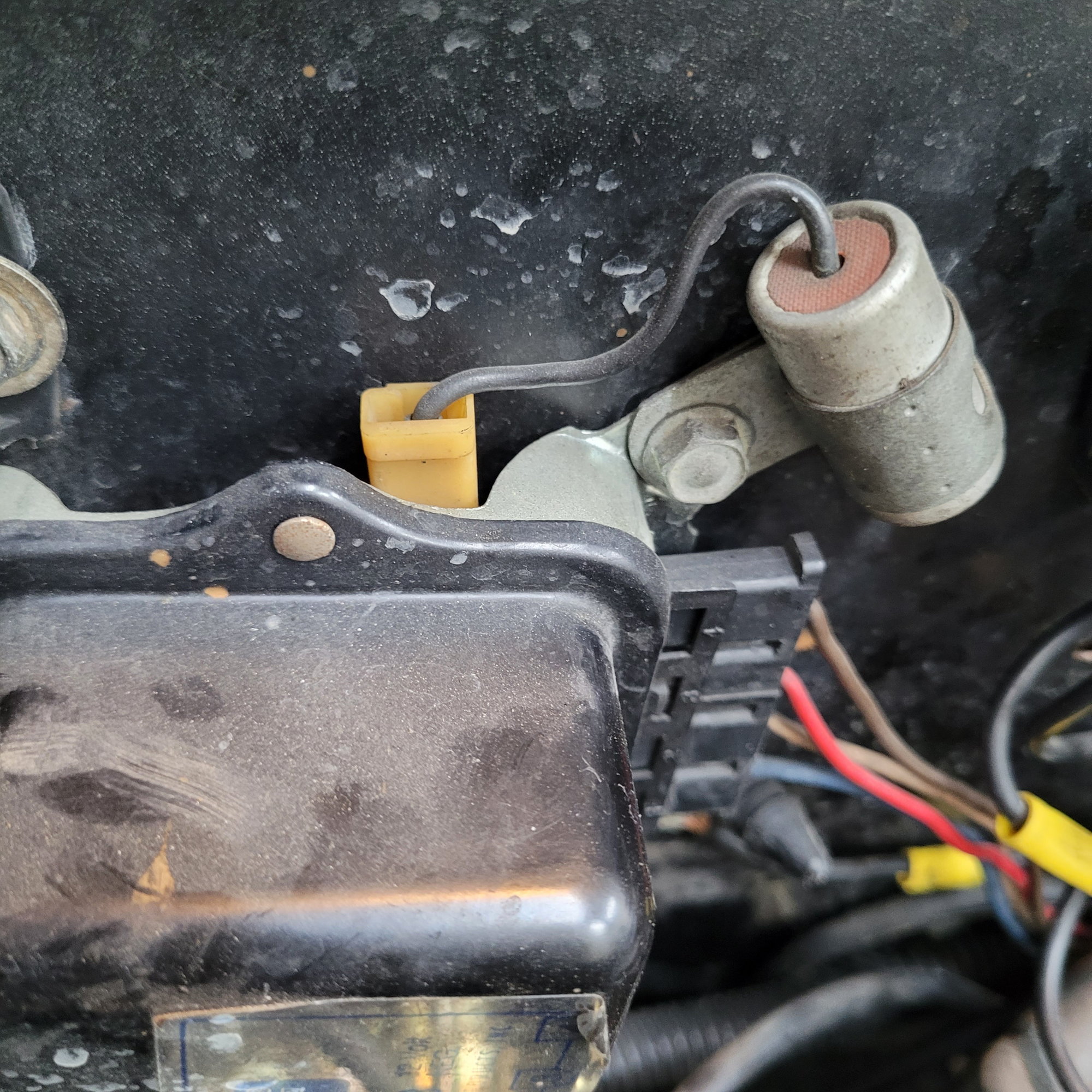
Does anyone have a photo showing the correct way to route the external voltage regulator capacitor wire? This is for a 72 Cutlass with rear the rear window defogger grid and no A/C.
Warren Seale is offline  
Old January 24th, 2022, 07:50 AM
  #2  
Old(s)GuysRule
 
67OAI's Avatar
 
Join Date: Apr 2016
Location: S.E.Georgia
Posts: 1,076
Do you have the mechanical voltage regulator or an electronic (transistorized) replacement?
67OAI is offline  
Old January 24th, 2022, 09:15 AM
  #3  
Old(s)GuysRule
 
67OAI's Avatar
 
Join Date: Apr 2016
Location: S.E.Georgia
Posts: 1,076
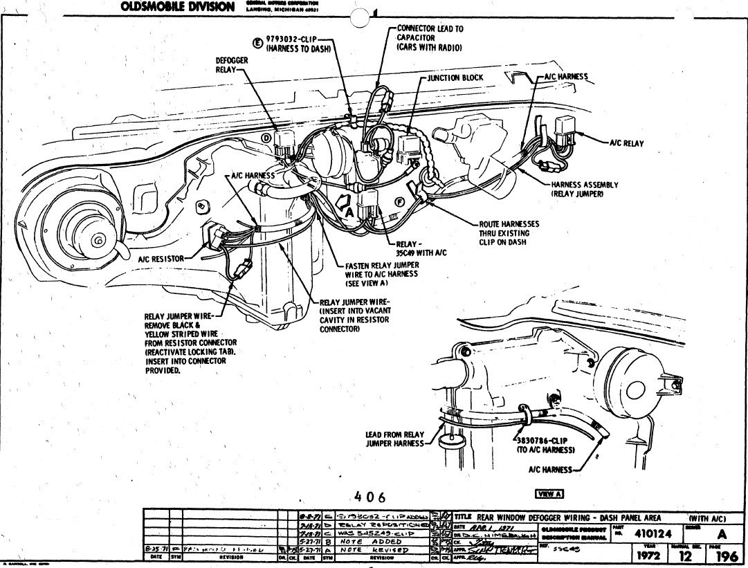
Portion of the wiring diagram shown as a "sticky" in the "Electrical" forum; if you have the transistorized VR, no capacitor is needed.

67OAI is offline  
Old January 24th, 2022, 10:02 AM
  #4  
Registered User
 
ART T's Avatar
 
Join Date: Aug 2011
Location: St. Petersburg, Fl
Posts: 129
Will the capacitor harm the ER?
ART T is offline  
Old January 24th, 2022, 02:42 PM
  #5  
Registered User
 
Tri-Carb's Avatar
 
Join Date: Apr 2020
Posts: 693
The capacitor attached to the case on the external, mechanical voltage regulator performs two functions. It suppresses EMP when the regulator contacts open so you do not hear it in the audio circuit of your radio. ( EEs would say that say that it adds VARs to a transient circuit whose Thevenin equivalent circuit appears biased towards the inductive side.) And it suppresses the electric arc created when the contacts open and thereby enhances their longevity.

When you go the solid state style regulators, the mechanical switching is eliminated.

Last edited by Tri-Carb; January 24th, 2022 at 02:45 PM.
Tri-Carb is offline  
Old January 24th, 2022, 03:06 PM
  #6  
Registered User
 
ART T's Avatar
 
Join Date: Aug 2011
Location: St. Petersburg, Fl
Posts: 129
Thank you.
ART T is offline  
Old January 24th, 2022, 04:03 PM
  #7  
Running On Empty
 
Vintage Chief's Avatar
 
Join Date: Jul 2018
Location: Earth
Posts: 18,085
Originally Posted by ART T
Thank you.
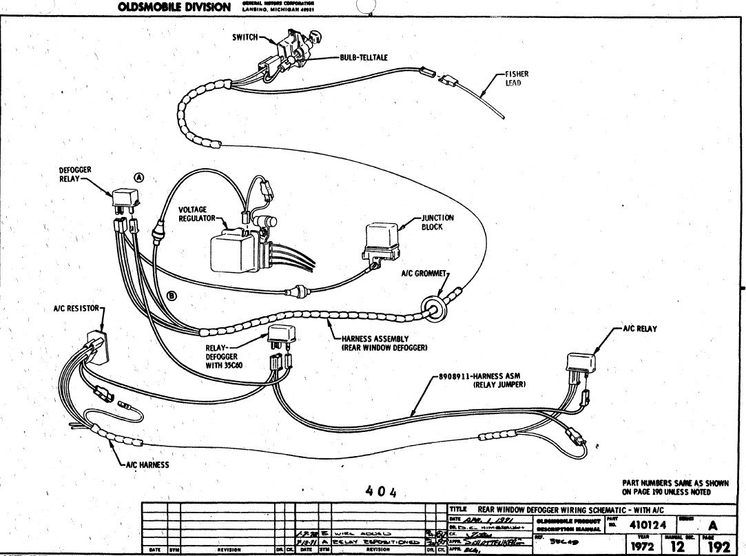
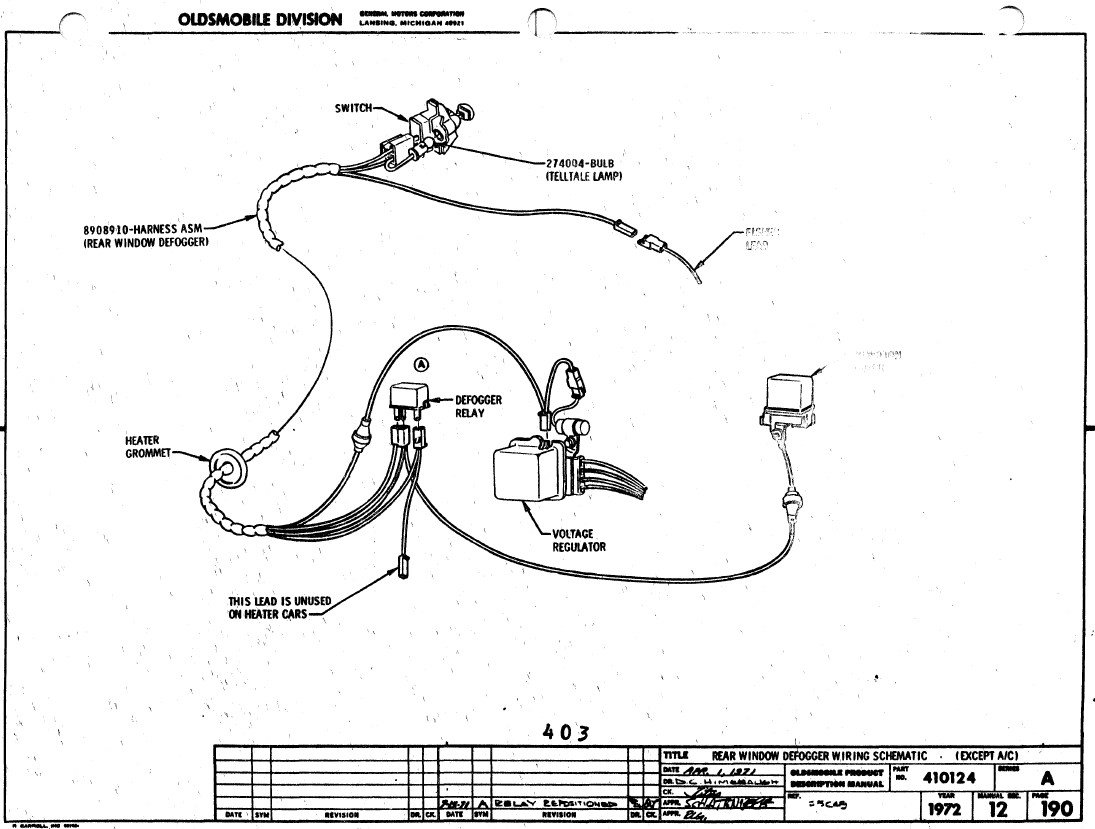
Do you have the PIM? I have the '72 PIM which demonstrates a wiring diagram including the various relays, window defogger, VR & capacitor. You want that or are you good?
Vintage Chief is offline  
Old January 24th, 2022, 04:15 PM
  #8  
Running On Empty
 
Vintage Chief's Avatar
 
Join Date: Jul 2018
Location: Earth
Posts: 18,085
Here, I'll toss these up for you. I think you might one or two helpful. NOTE: I didn't review each for detail but I noted there may be a delta w/ AC vs. w/o AC.


Vintage Chief is offline  
Old January 24th, 2022, 05:05 PM
  #9  
Registered User
 
ART T's Avatar
 
Join Date: Aug 2011
Location: St. Petersburg, Fl
Posts: 129
Thanks, I'm good. I changed to an electronic one when I read that it could spike and take out the module in the HEI.
ART T is offline  
Old January 24th, 2022, 05:58 PM
  #10  
Running On Empty
 
Vintage Chief's Avatar
 
Join Date: Jul 2018
Location: Earth
Posts: 18,085
The OP asked for photos perhaps they’ll assist.
Vintage Chief is offline  
Old January 24th, 2022, 06:49 PM
  #11  
Registered User
 
Loaded68W34's Avatar
 
Join Date: Jul 2020
Location: Pennsylvania
Posts: 1,575
The bigger question is how was the grid defroster wired when ordered on a 442? I have looked in the PIM and have not found anything. The purpose of the wire running off of the capacitor lead on the voltage regulator is to only allow the grid to be on while the engine is running (regulator & alternator are charging), but I cannot find any reference to how the system was wired on a 442 which would have an open face internally regulated alternator and no voltage regulator on the firewall. Ideas?
Loaded68W34 is offline  
Old January 24th, 2022, 09:10 PM
  #12  
Registered User
 
Fun71's Avatar
 
Join Date: Feb 2013
Location: Phoenix, AZ
Posts: 13,782
Originally Posted by ART T
Thanks, I'm good. I changed to an electronic one when I read that it could spike and take out the module in the HEI.
I think that is a non-issue. My car has worked just fine with a GM HEI along with a mechanical voltage regulator since 1982 and it’s still on the same ignition module. Now the voltage regulator failed twice during that time, and I repaired it and put it back into service.
If a totally failed voltage regulator doesn’t take out the ignition module, I doubt a transient voltage spike would.

Last edited by Fun71; January 24th, 2022 at 09:12 PM.
Fun71 is online now  
Old January 24th, 2022, 10:55 PM
  #13  
Registered User
 
OldOldsLover's Avatar
 
Join Date: Jan 2022
Location: Las Vegas Nevada
Posts: 79
Originally Posted by Warren Seale
Does anyone have a photo showing the correct way to route the external voltage regulator capacitor wire? This is for a 72 Cutlass with rear the rear window defogger grid and no A/C.


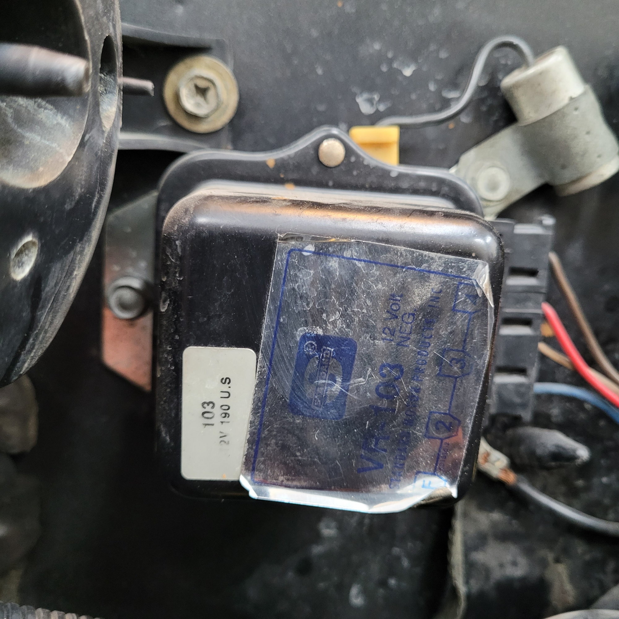
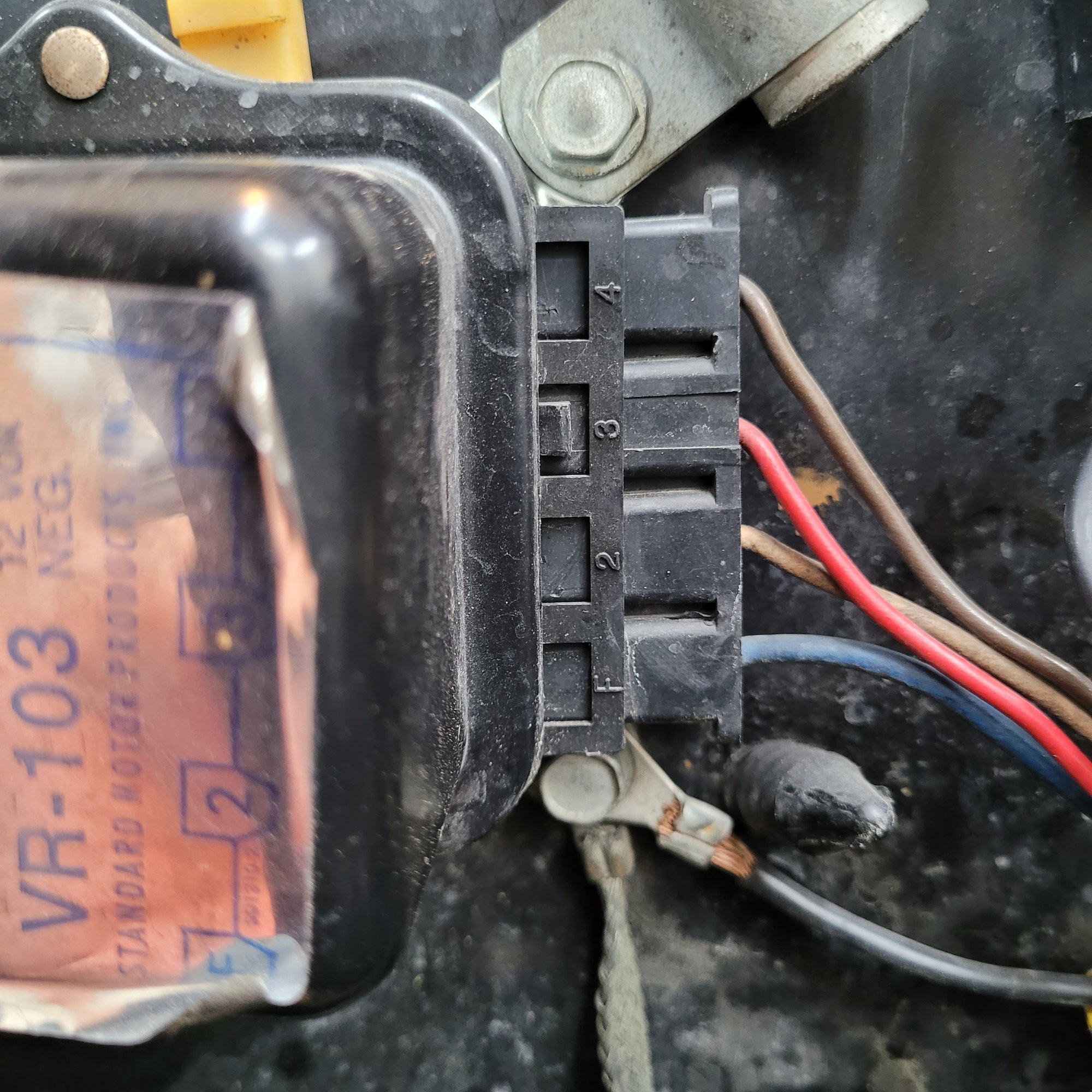
1972 Cutlass Supreme without rear defroster and with air conditioning. Hope it helps.

Last edited by OldOldsLover; January 24th, 2022 at 11:00 PM. Reason: Add text
OldOldsLover is offline  
Old January 25th, 2022, 11:27 AM
  #14  
Registered User
Thread Starter
 
Warren Seale's Avatar
 
Join Date: Aug 2013
Posts: 136
Can I assume that the photos above show the original factory routing? So, the wire feeding the capacitor runs behind the voltage regulator?

The illustrations show the wire just flying in the air. This is probably not correct but necessary to show how the wires are interconnected.
Warren Seale is offline  
Old January 25th, 2022, 11:32 AM
  #15  
Registered User
Thread Starter
 
Warren Seale's Avatar
 
Join Date: Aug 2013
Posts: 136
Originally Posted by 67OAI
Do you have the mechanical voltage regulator or an electronic (transistorized) replacement?
Mechanical.
Warren Seale is offline  
Old January 25th, 2022, 11:48 AM
  #16  
Registered User
 
OldOldsLover's Avatar
 
Join Date: Jan 2022
Location: Las Vegas Nevada
Posts: 79
Originally Posted by Warren Seale
Can I assume that the photos above show the original factory routing? So, the wire feeding the capacitor runs behind the voltage regulator?.
I believe this is the way it came from the factory.


OldOldsLover is offline  
Old January 25th, 2022, 11:52 AM
  #17  
Registered User
 
Loaded68W34's Avatar
 
Join Date: Jul 2020
Location: Pennsylvania
Posts: 1,575
Originally Posted by Warren Seale
Can I assume that the photos above show the original factory routing? So, the wire feeding the capacitor runs behind the voltage regulator?

The illustrations show the wire just flying in the air. This is probably not correct but necessary to show how the wires are interconnected.
No,
The photos show a capacitor and regulator in a system without a rear defroster but with A/C (exactly the opposite of what you are looking for). The defroster wiring shown in the diagrams is correct (although the wire may not be positioned that high). The capacitor wire on the rear defroster cars ensures that the grid will only be on while the car is running (while the system is charging). So, even if the ignition is on, if the car is not running the grid will not turn on. The main power feeding the relay comes off of the horn relay junction as seen in the diagram, but the wire providing power to the switch in the dash that turns the relay on comes from the terminal on the voltage regulator that would normally just have a capacitor plugged into it. The photos show the regular system where only a capacitor is plugged onto the voltage regulator not the defroster harness.
Loaded68W34 is offline  
Related Topics
Thread
Thread Starter
Forum
Replies
Last Post
ostie13
Electrical
6
September 8th, 2014 04:41 AM
Jacob Wilson
Electrical
6
December 2nd, 2013 12:59 AM
yeahbuddy
Electrical
26
December 1st, 2011 10:29 PM
442_Mustang
Electrical
8
May 25th, 2010 07:31 PM
and1stp
Electrical
2
September 17th, 2006 07:31 PM


Quick Reply: external voltage regulator capacitor wire routing


All times are GMT -7. The time now is 01:49 PM.